Multimodal inspection / Guide 94
Printed-Part Scan Comparison Needs Datums and an Unknown State
Compare printed-part scans with CAD using explicit datums, revision identity, uncertainty bounds, and surface coverage before engineers approve inspection findings.
Illustrative engineering guide. Examples are not client deployments, production-ready integrations, or evidence of measured results. Validate the design with your domain and security owners.

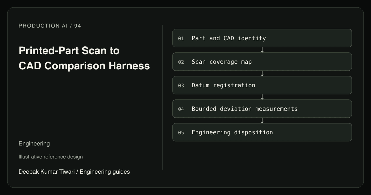
A hypothetical scan of a printed bracket looks almost identical to its CAD model. An unconstrained best fit rotates the scan until most surfaces align, hiding a tilted mounting face that matters in the assembly. Meanwhile, the bore interior was never scanned. Calling the part within tolerance would confuse attractive alignment with a complete dimensional inspection. The harness must preserve functional datums and unobserved surfaces.
The raw inputs are scanner observations, optional photographs, and a released CAD representation. A model may suggest warping or identify a likely mounting face. A specialist measurement engine should perform registration and surface comparison, while an engineer decides whether the inspection method and coverage answer the actual drawing requirements. Neither a language model nor a geometry library supplies infallible physical ground truth.
Define What Is Being Compared
Record part serial, build job, material batch, postprocessing state, scan session, scanner configuration, calibration certificate reference, and CAD revision digest. A scan before support removal cannot be compared with a finished-part acceptance plan without identifying those extra surfaces. A nominal model may also omit drawing tolerances; the engineer must provide the actual inspection requirements separately.
Store raw scan coordinates with units before normalization. Convert through a documented transform chain into a right-handed part datum frame in millimeters, with the mounting face defining the primary datum and an approved feature fixing orientation. Retain transform direction, handedness, scale conversion, and numerical precision. A millimeter-to-meter mistake should fail a known check length before any color deviation map is produced.
For supporting images, preserve camera identifier, image digest, capture time, crop mapping, and top-left pixel axes. OpenCV’s calibration tutorial explains why image points require known object geometry for calibrated reconstruction. Photographs help reviewers understand surface finish and occlusion; an uncalibrated photograph must not become the source of a claimed bore diameter.
Do Not Fit Away the Defect
Open3D’s ICP registration tutorial starts from an initial alignment and describes iterative refinement. That is useful computational machinery, not a decision about which part features are allowed to move. Constrain registration using the inspection datum scheme, record independent check residuals, and compare against a diagnostic best fit without substituting it for the contractual alignment.
Specify the distance definition. Nearest-surface distance, signed normal deviation, and diameter error answer different questions. Open3D’s distance query documentation notes that signed distance and occupancy require a watertight mesh with a well-defined inside and outside. An open scan surface does not magically satisfy that assumption. Use unsigned distances or an appropriate specialist method when the sign is not meaningful.
Coverage belongs to CAD feature regions or area cells selected before seeing the scan. Counting dense scanner points favors easy reflective surfaces and hides missing bore walls. Mark each required cell observed, excluded under an approved rule, or unknown. Interpolation across a hole may create a pleasant mesh but cannot create inspection evidence for the missing region.
Test Interval Classification
This self-contained Python fixture tests the HARNESS on synthetic structured measurements. It does not run a trained vision model, camera, scanner, CAD engine, registration algorithm, or real inspection. The deviations are supplied as if a specialist adapter had already calculated them. The 0.5 millimeter tolerance and 0.2 millimeter registration budget are illustrative policy values, not drawing requirements.
from math import isfinite

base = dict(cad="bracket-r8", frame="datum-ABC-mm", observed=True,
            deviation_mm=0.15, bound_mm=0.1, registration_mm=0.05)

def assess(row):
    if (row["cad"], row["frame"]) != ("bracket-r8", "datum-ABC-mm"):
        return "invalid-comparison"
    if not row["observed"]:
        return "unknown"
    d, u, r = (row["deviation_mm"], row["bound_mm"], row["registration_mm"])
    if not all(isfinite(v) for v in (d, u, r)) or min(u, r) < 0 or r > 0.2:
        return "unknown"
    total_bound = u + r
    if abs(d) - total_bound > 0.5:
        return "deviation-review"
    return "within-band-evidence" if abs(d) + total_bound <= 0.5 else "uncertain"

assert assess(base) == "within-band-evidence"
assert assess(dict(base, deviation_mm=0.8)) == "deviation-review"
assert assess(dict(base, deviation_mm=0.45)) == "uncertain"
assert assess(dict(base, observed=False)) == "unknown"
assert assess(dict(base, registration_mm=0.3)) == "unknown"
assert assess(dict(base, frame="scanner-m")) == "invalid-comparison"
print("six synthetic deviation checks passed")
Adding bounds conservatively assumes their stated magnitudes are valid limits; it is not a statistical confidence calculation. A real uncertainty budget must include scanner calibration, surface interaction, fixture repeatability, tessellation, and registration, without double counting. If estimates are statistical rather than bounded, a metrologist must select and document the propagation method. The code only verifies the stated interval policy.
Within-band evidence is intentionally not named pass. A supported external face cannot release an unmeasured bore, and dimensional agreement cannot establish strength, adhesion between layers, internal voids, fatigue life, or material identity. Functional testing and other inspection methods remain separate requirements. The review packet should show those limitations beside the colored surface map, not bury them in an export footer.
Disposition and Reinspection
An engineer receives the part identity, datum diagram, raw scan references, measurement method version, regional coverage, and intervals for each reported deviation. They can request a fixture change, a targeted rescan, or contact metrology for a functional feature. A disagreement between scan and caliper measurements is a reason to investigate the methods, not average their values automatically.
Maintain server-side access boundaries around customer CAD and scan data. Treat embedded filenames and annotations as untrusted content. An assistant can draft a nonconformance report but cannot modify the released CAD or approve a concession. Persist approved tickets with part, feature, CAD revision, and evidence digest; reconcile timeouts before retries. Superseded scans stay traceable instead of disappearing when a better result arrives.
The data quality workflow is useful for rejecting mixed units and stale identifiers before computation. A measurement job should become invalid if its CAD digest changes, even if the friendly revision label remains the same. Production dependencies omitted by the fixture include artifact authentication, complete schema validation, geometry kernels, uncertainty estimation, and durable approval state.
Acceptance Tests and Evaluation
- Leave the bore interior unscanned; its region remains unknown despite a complete exterior mesh.
- Register on the wrong repeated hole; independent datum checks invalidate the comparison.
- Provide scanner coordinates in meters with a millimeter frame label; a known check length catches the scale mismatch.
- Move a deviation interval across the tolerance boundary; classify it uncertain rather than rounding toward acceptance.
- Compare a support-covered specimen with a finished-part plan; require a postprocessing-state review.
- Use an open mesh for signed distance; reject the unsupported sign interpretation or switch to an approved method.
Baseline against an engineer-approved metrology method on distinct physical specimens. Report correctly identified out-of-band features divided by all adjudicated out-of-band features, false deviation reports divided by all reports, and observed required area divided by total required area. Keep missing regions in the denominator. Split evaluation by build job and scan session to prevent repeated captures from masquerading as new specimens.
Start with one bracket family and a datum fixture, not arbitrary uploaded meshes. Printer failure detection handles a different question during production and cannot replace finished-part inspection. A focused AI systems project should first make comparison identity and regional unknowns reproducible; sophisticated narration comes after the measurement contract works.